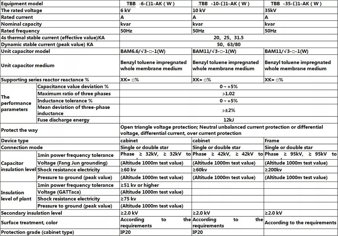
 1. The rated working voltage is 10kV, and it can run for a long time at 11 times the rated voltage. 2. When the root mean square value does not exceed 1.3Un, the device can operate continuously at rated frequency, rated sinusoidal voltage and current generated by no transition state. 3. The device is provided with over-current, over-voltage, under-voltage protection for system faults. 4. For the protection of the internal fault of the capacitor, in addition to the fuse protection for a single unit, different relay protections are also provided according to the different main wiring forms. 5. The design and processing of the device conform to GB50227-1995 "Design Specification for Parallel Capacitor Device" and JB71 1-1 993 "High Voltage Parallel Capacitor Device".
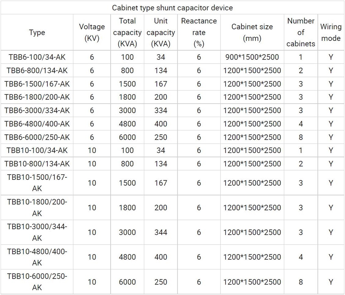
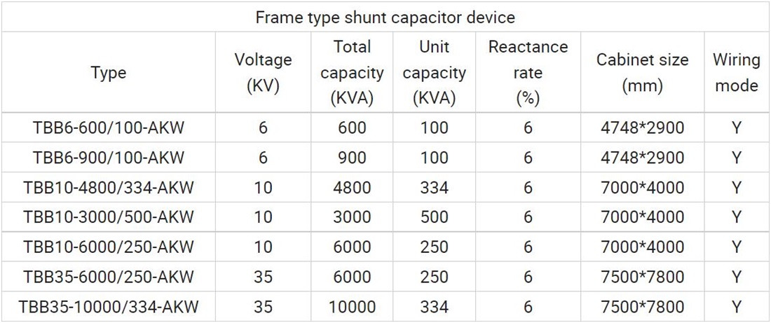
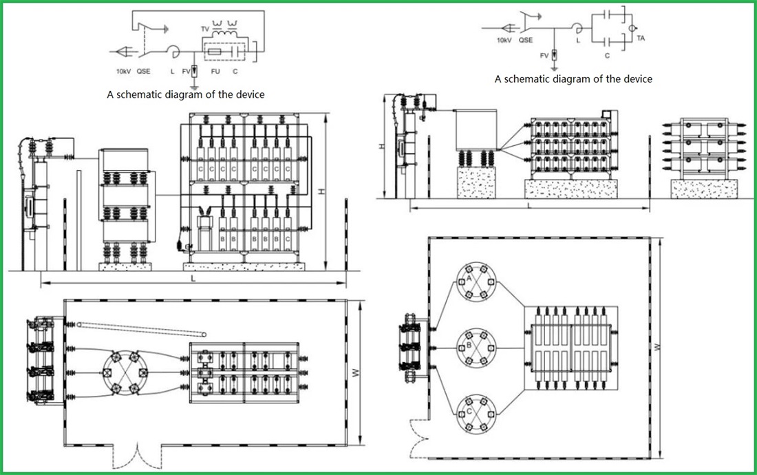
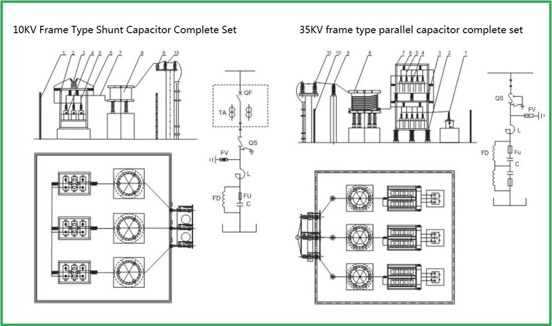
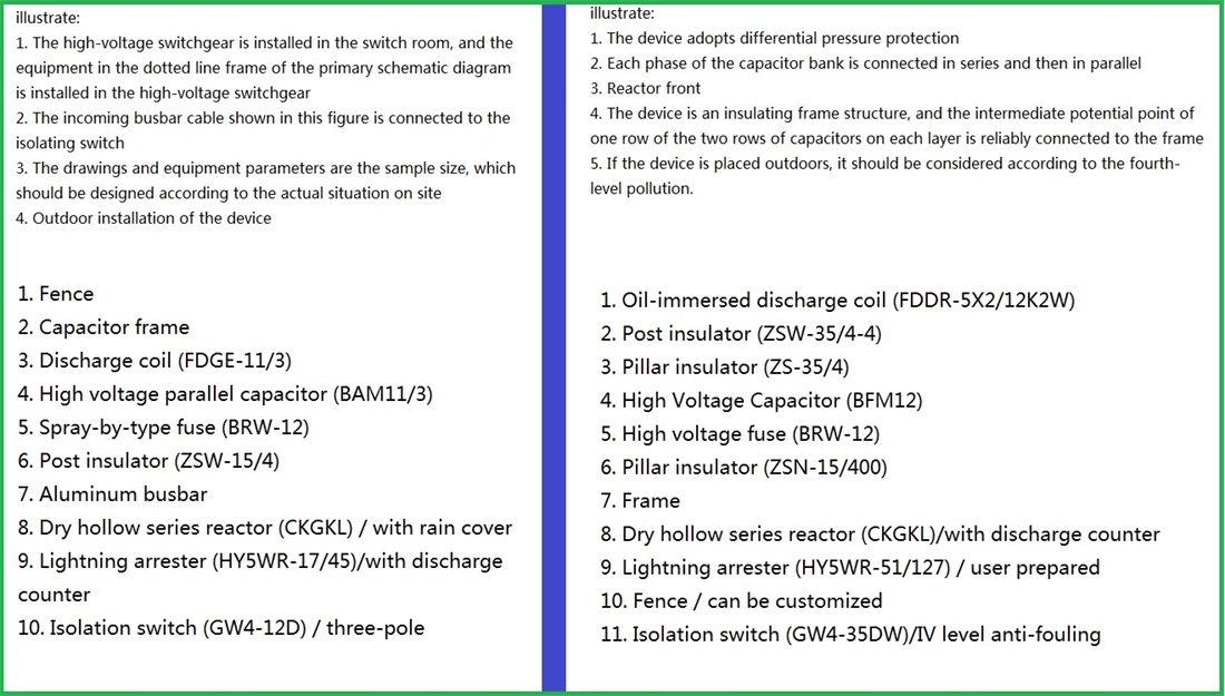
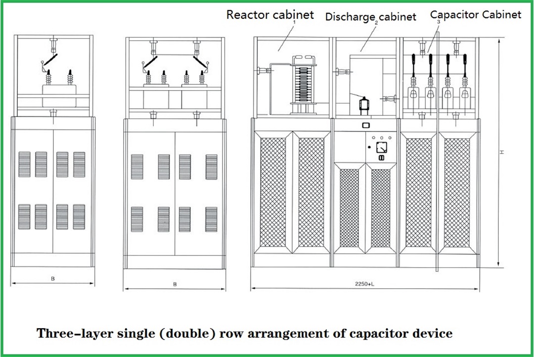
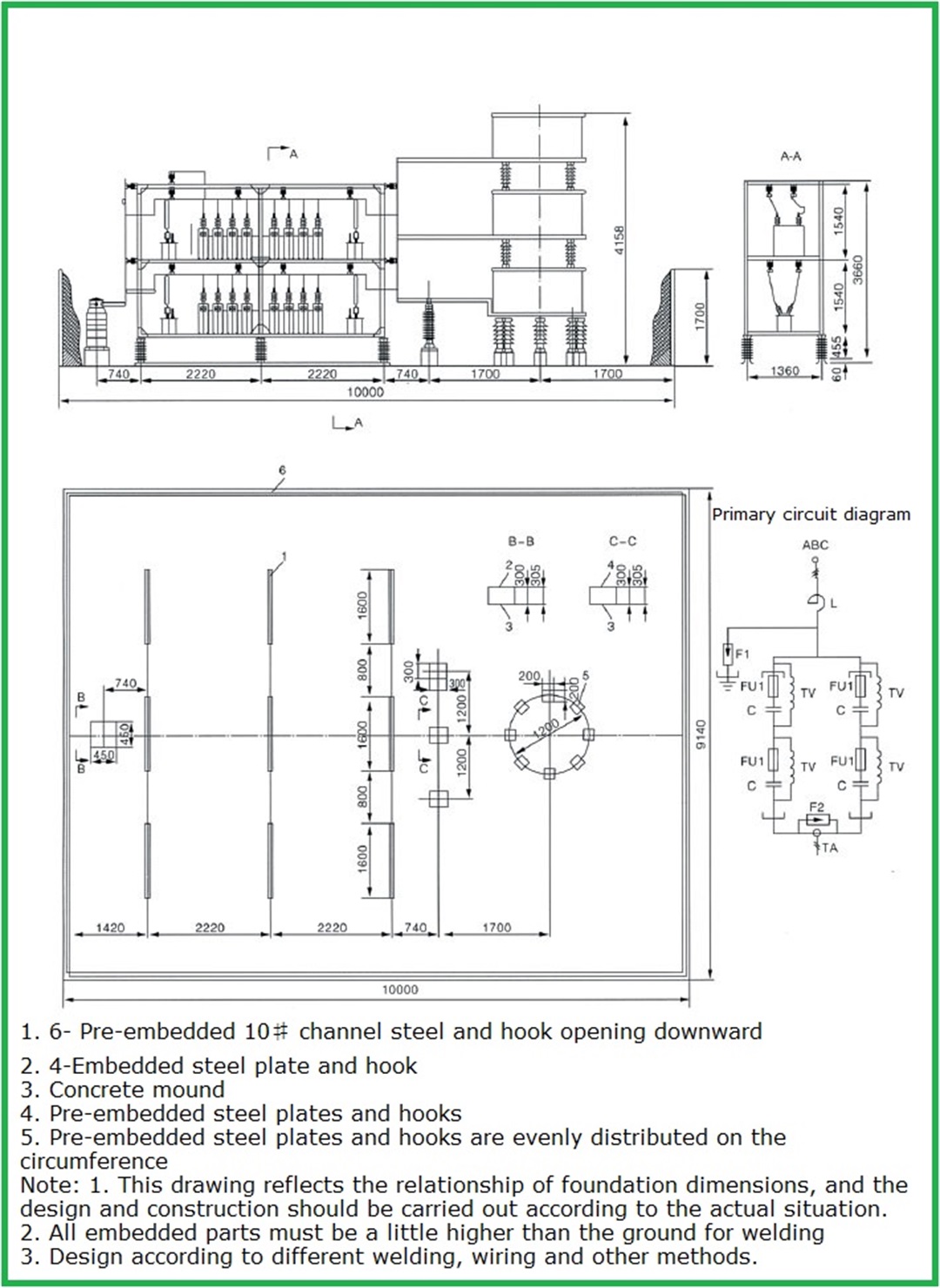
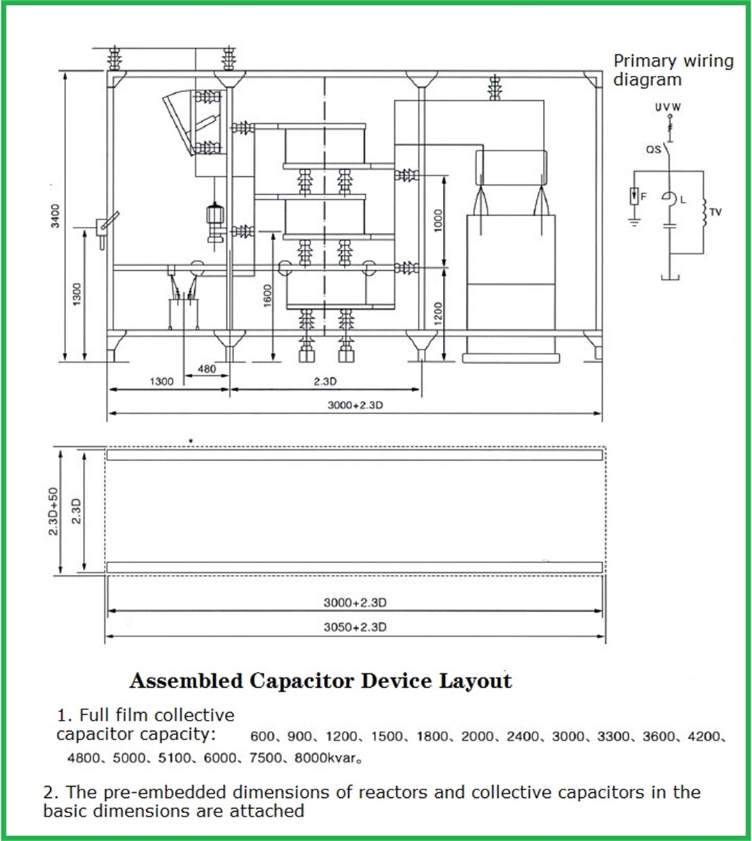
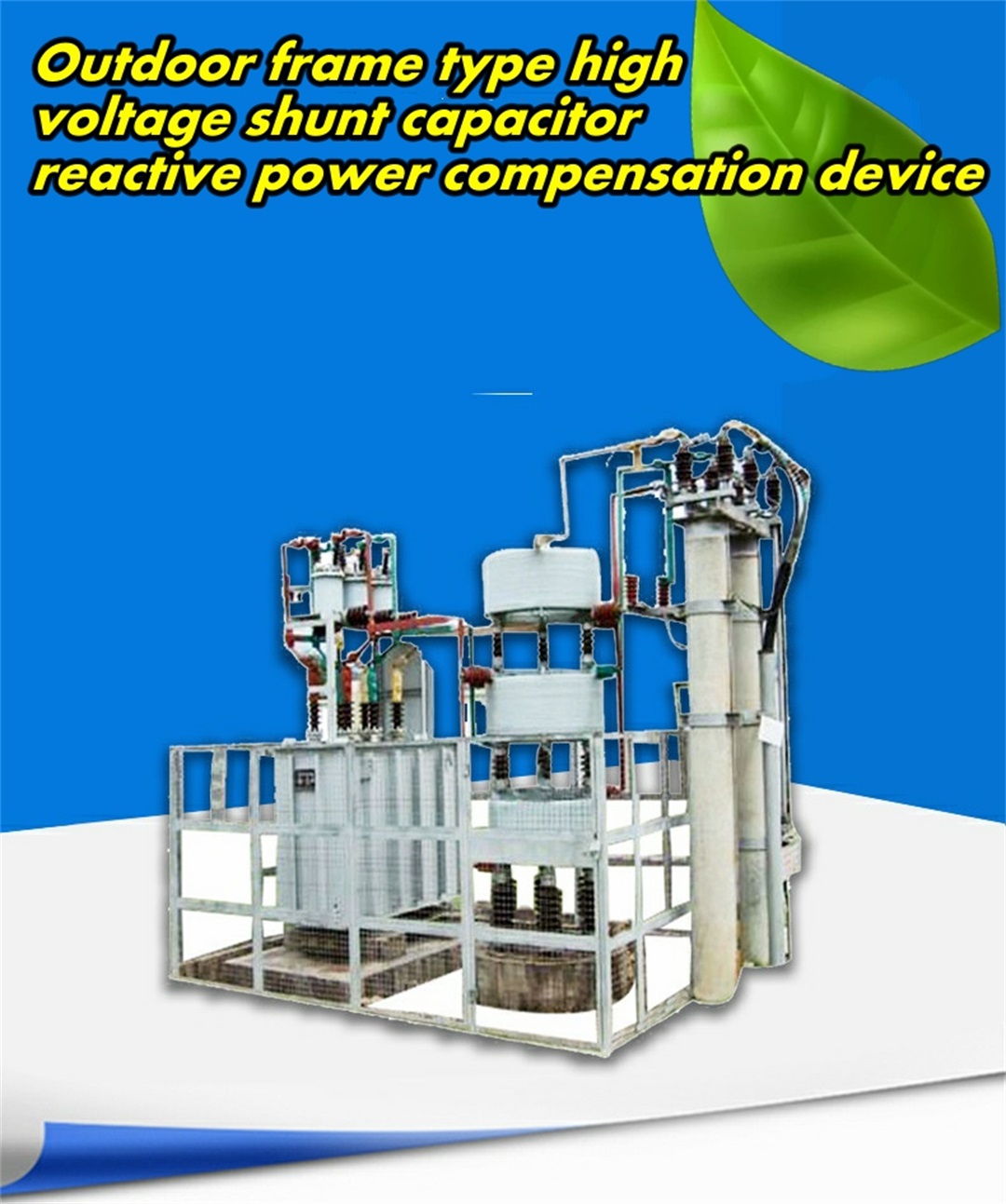
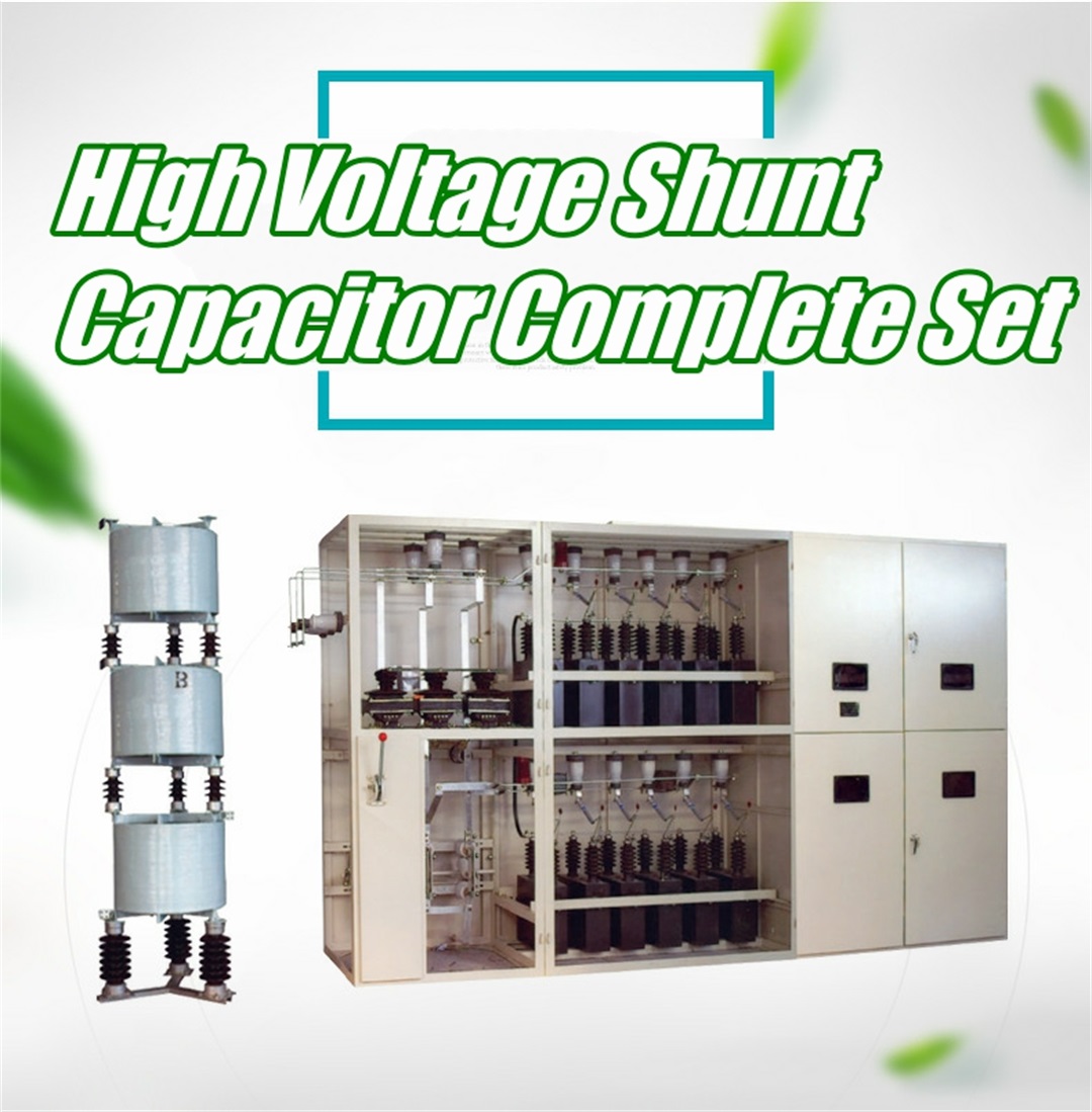
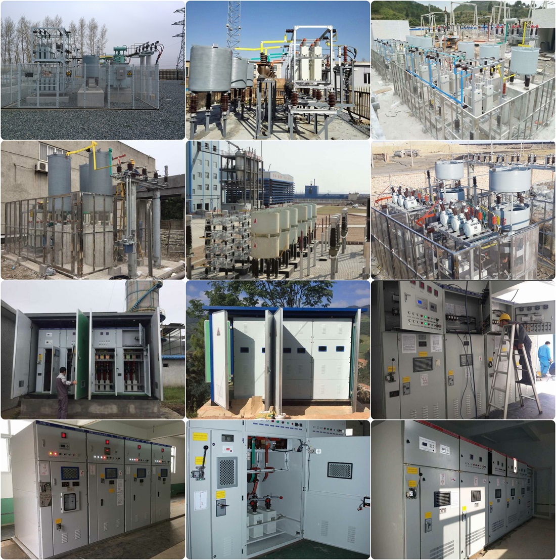
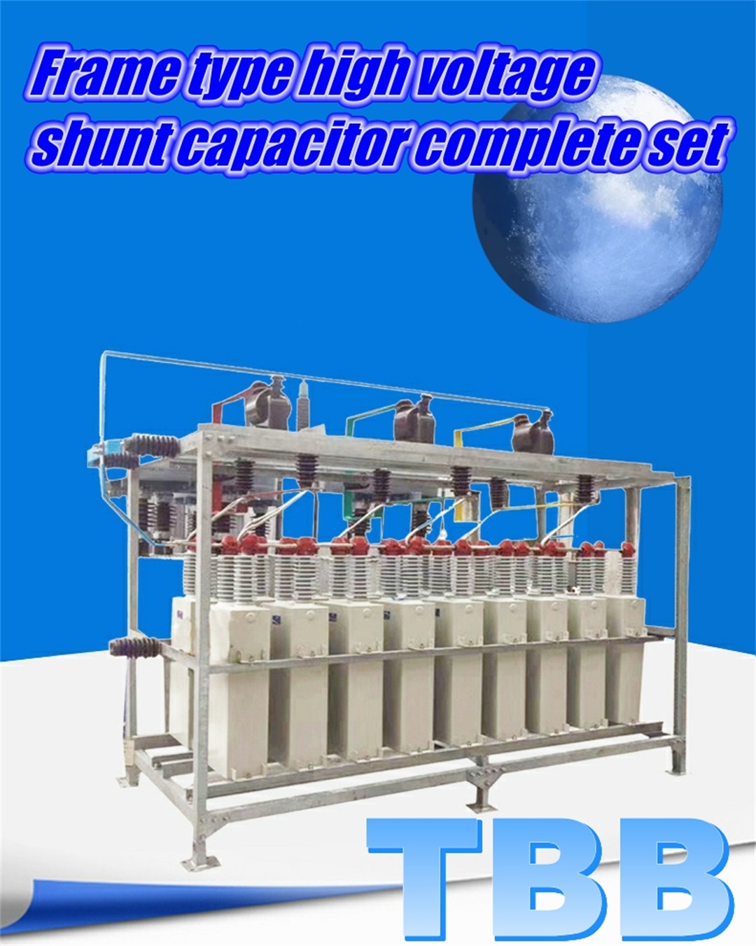
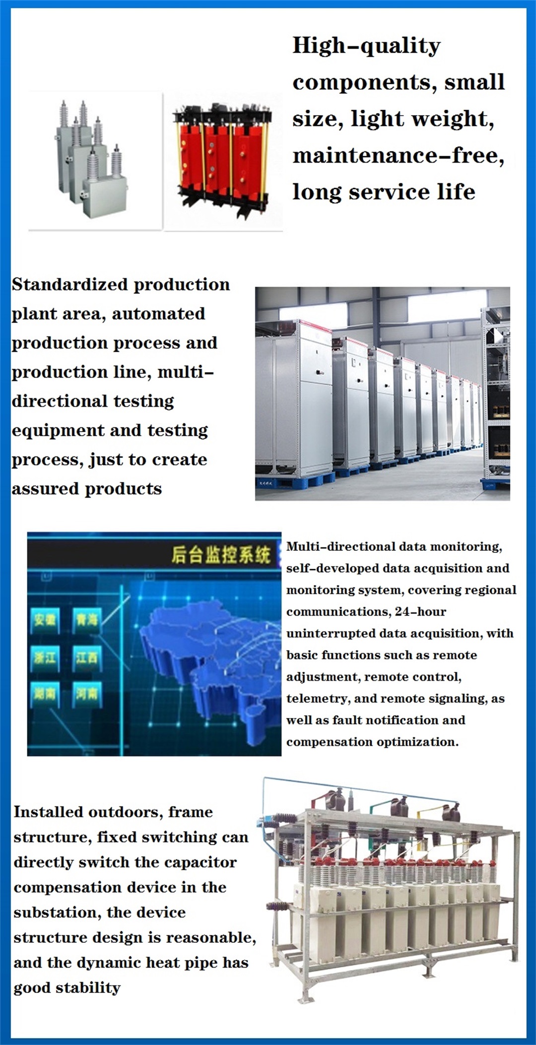
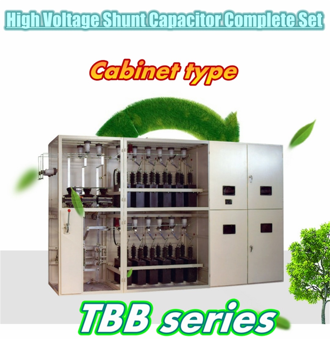
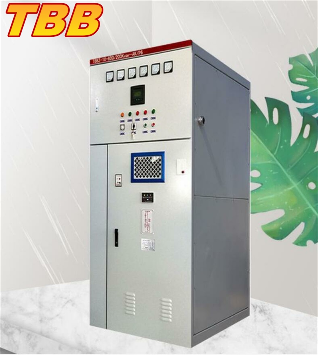 Features: 1. The device can operate for a long time under the steady-state overvoltage of 1.1 times the rated voltage; 2. The device can run continuously under the overcurrent whose root mean square value does not exceed 1.3 times the rated current of the capacitor bank; 3. The device adopts a high-voltage circuit breaker without heavy, and is equipped with an oxidized breakdownd cast arrester to limit the operating overvoltage generated when switching capacitor banks; 4. For 6kV and 10kV devices, vacuum load switch, vacuum circuit breaker or SF6 type circuit breaker is used as the switching switch of the capacitor bank. For capacitor banks with small capacitance, vacuum contactors should be used for group switching, and vacuum circuit breakers or SF6 switches should be used for capacitor banks with large capacitance; 5. The device selects a dry-type air-core reactor connected to the power supply side of the device or a dry-type iron-core reactor connected to the neutral point side of the device to limit the closing inrush current, suppress high- order harmonics, and improve the network voltage waveform. A reactor with a rated reactance rate of 0.5-1% is used to limit the closing inrush current; a reactor with a rated reactance rate of 5-6% is used to suppress the 5th and above harmonics and limit the closing inrush current; the rated reactance rate is 12-13%. Used to suppress 3rd and above harmonics and limit closing inrush current; 6. The device adopts FDGR type discharge coil, which can reduce the residual of the capacitor bank from the peak value of the rated voltage to below 0.1 times the rated voltage within 5s; 7. According to the needs of the system and users, the device can adopt local control or main control room, centralized control or automatic control; 8. The voltage protection adopts single capacitor fuse protection as the main protection, open triangle, voltage differential, neutral line unbalanced current as backup protection, in addition, the device is also equipped with overcurrent, overvoltage and voltage loss protection. The realization of These protections can also choose a microcomputer capacitor protection monitoring device with better performance to achieve the requirements for capacitor relay protection. Structural features: 1. The 6~1OkV device consists of high-voltage switchgear (including circuit breakers, high-voltage isolation switches, current transformers, relay protection, measuring instruments), series reactors, discharge coils, zinc oxide arresters, grounding switches, and single capacitor protection. It consists of fuse, parallel capacitor, connecting busbar and steel structure frame. The double star also includes a current transformer for neutral line unbalanced current protection. 2. The high-voltage switch cabinet of 6~1OkV device is installed in the switch room. The arrangement of capacitor banks and series reactors is divided into three types: indoor cabinet type, frame type and collective type. a. Indoor cabinet type The capacitor bank is composed of one incoming cabinet and several capacitor cabinets according to different capacity specifications. Discharge coils, grounding switches and oxidation arresters are installed in the incoming cabinet. The capacitor cabinet includes parallel capacitors, a single capacitor protection fuse, and a transparent capacitor observation window on the door panel. b. Frame type The capacitor bank includes the inlet frame and the capacitor frame. The entire device framework is divided into several panels, which are then assembled on site. The wire frame is equipped with discharge coil, grounding switch and oxidation arrester. The double star connection also has a current transformer for neutral line unbalanced current protection. The capacitor structure includes parallel capacitors and fuses for single capacitor protection. Steel mesh fences can be set outside the frame or steel mesh doors can be set on the frame. c. Collective The collective type is a way of capacitor bank composed of collective parallel capacitors. Collective structure, including series reactor, collective parallel capacitor and discharge coil. 3. The 35kV device consists of high-voltage switchgear (including high-voltage circuit breakers, current transformers, relay protection, measurement and indication parts), series reactors, discharge coils, oxidized cast arresters, single protection fuses, parallel capacitors, etc. . Double star connection and current transformer for neutral line unbalanced current protection, all devices are frame structure. 4. Wiring of series reactor The air-core reactor is installed before the capacitor bank, that is, the power supply side, and the iron-core reactor is installed after the capacitor bank, that is, the neutral point side of the device. Use environment: 1. Altitude: not higher than 1000m; 2. Ambient temperature: -25℃~+55℃; 3. Relative humidity: no more than 85%; 4. The operation site is not allowed to
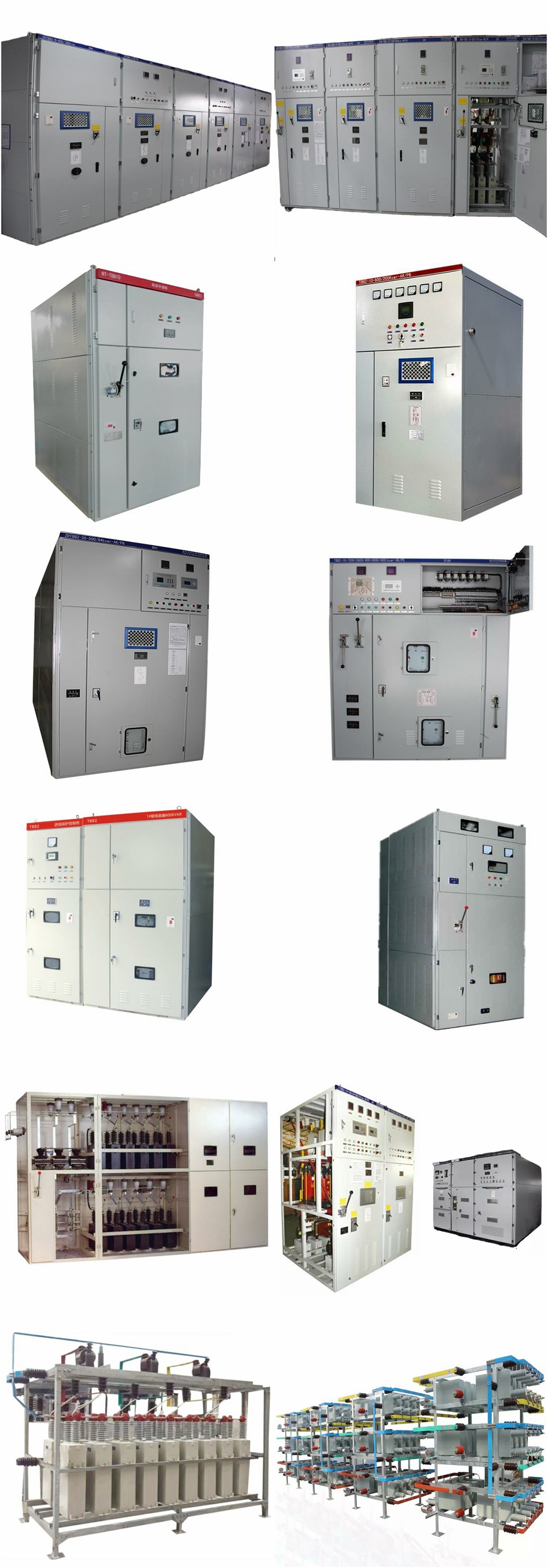
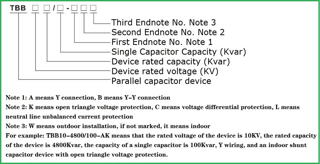
 1. Determine the required compensation capacity, the capacity of a single capacitor 2. Device model and corresponding serial number 3. Structure: cabinet type, cabinet type, collective type 4. The choice of reaction rate 5. Protection method 6. Other requirements